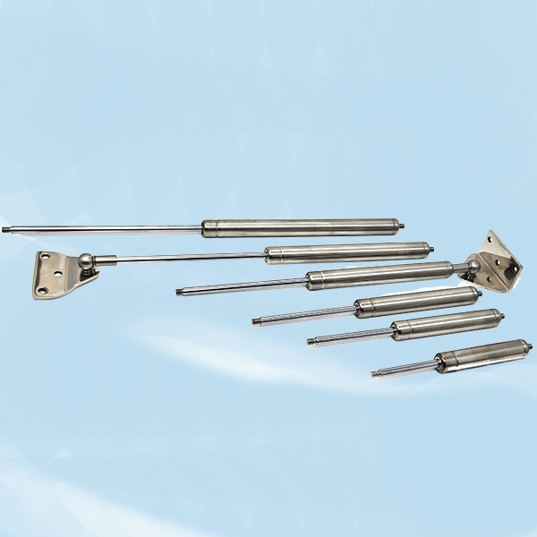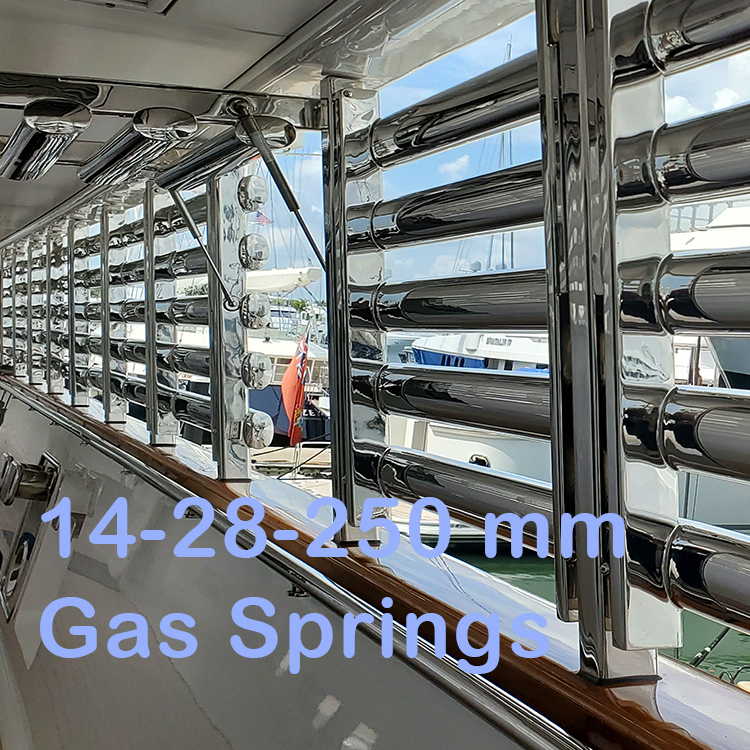
Gas Spring Series 14-28-250 mm. Each. Specify Newton Force Below
Specification

|
#61.425 |
14-28 |
“A” |
“B” |
62.123L |
62.127 |
62.135 |
62.140 |
|
|
Part ID |
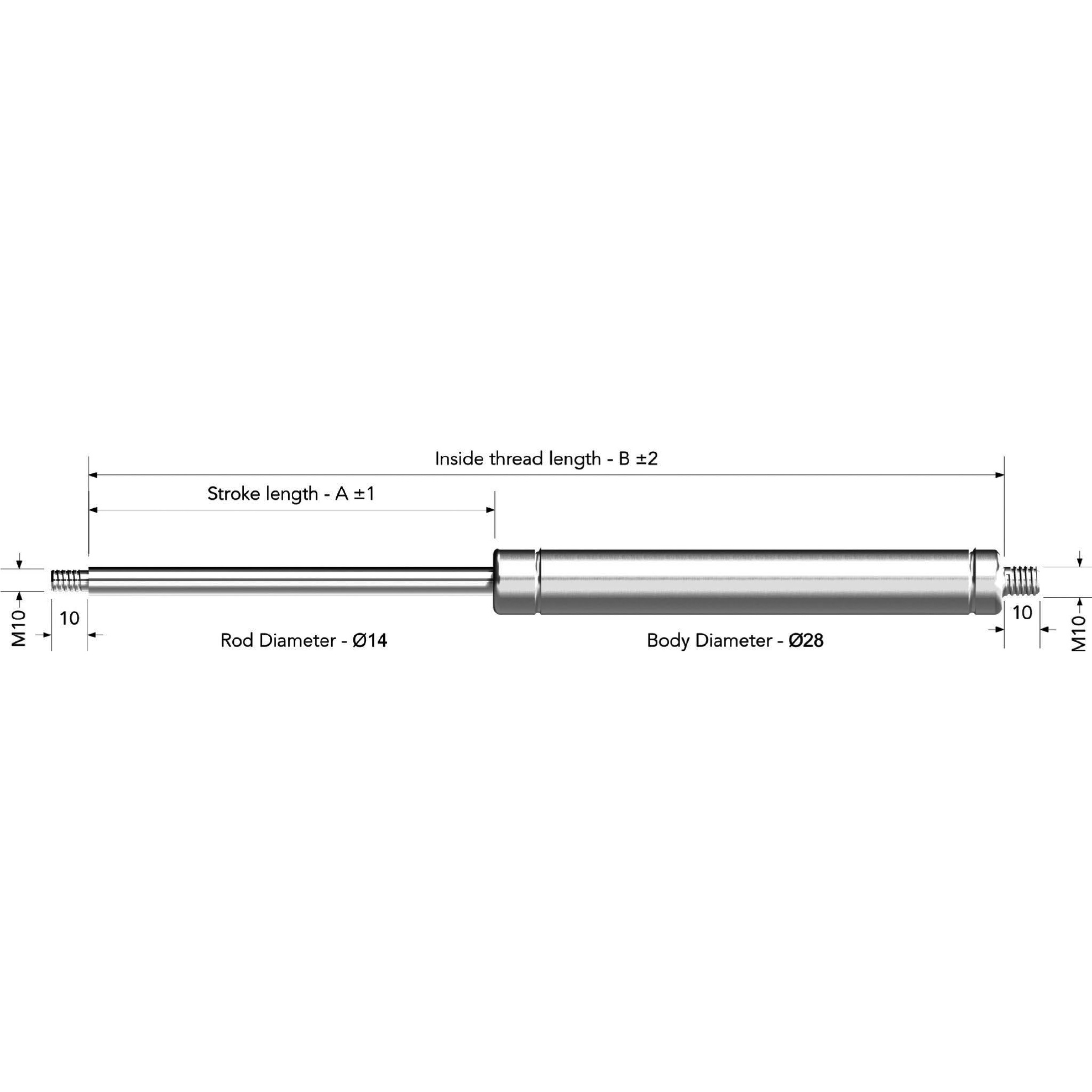
Series 14-28-stainless steel gas spring with valve |
Stroke Length in mm |
Total length without attachments (not counting the thread) 2 x stroke+ 50 mm) |
Short Eyes, add 2 x 23 mm |
Long Eyes, add 2 x 27 mm |
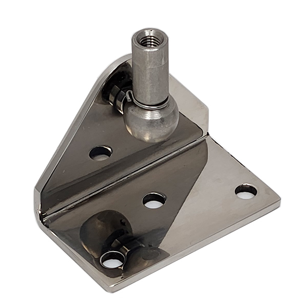
Ball Joints, add 2 x 35 mm |
Forks Add 2 x 40 mm |
Thread size and max. N force per rod length* |
|
14-28-250 |
Extended |
250 mm |
550 mm |
596 mm |
604 mm |
620 mm |
630 mm |
M10x1.5 – 2500N |
|
|
Compressed |
250 mm |
300 mm |
346 mm |
354 mm |
370 mm |
380 mm |
M10x1.5 – 2500N |
|
CHARGING TABLE CONVERTING FROM NEWTON TO PSI, BAR, KG AND LBS.
*Psi and Bar relates to the pressure inside the gas spring cylinder for this series. *Kg and Lbs relates to the weight balanced by a specific Newton for this series *Force For each application add 10% force to compensate for friction etc.
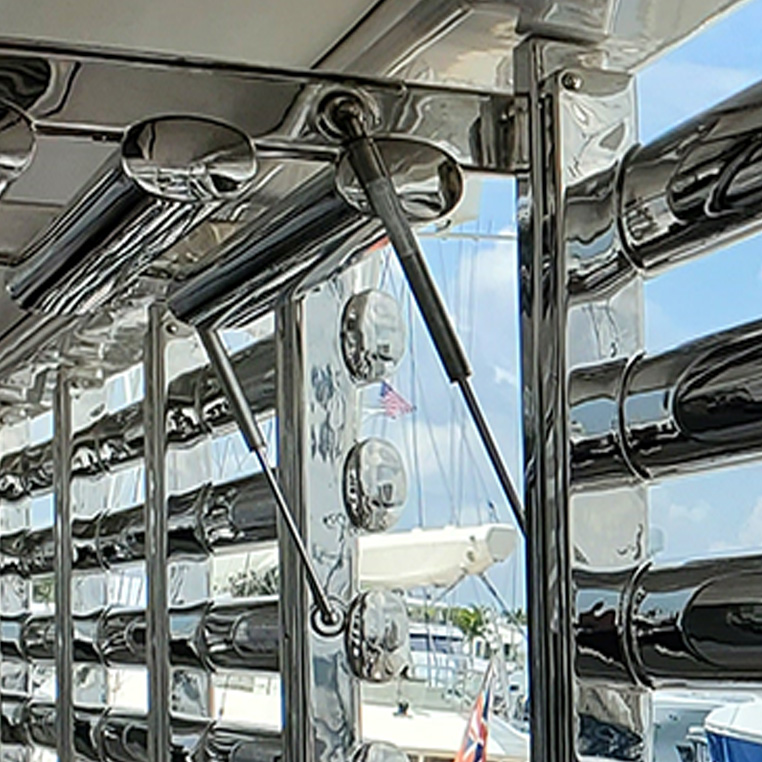
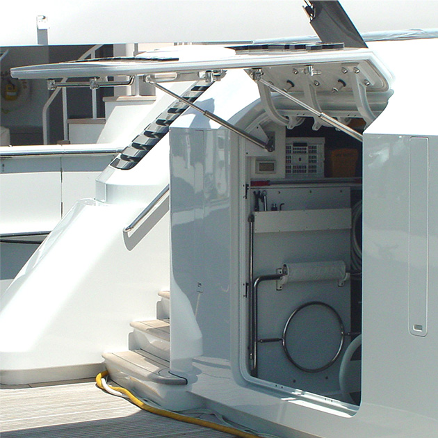
FORCE CALCULATION FOR HATCHES AS FOLLOWS: Use full scale drawings and engineering calculations to find the correct gas spring size and force for your application. GENERAL INFORMATION: Install the gas spring as far away as possible from the hinge within the range of the stroke. Please note: Torque on the hinges will be at least be twice the force of the weight of the hatch. Use incremental lesser force for gas springs when hatch is lighter. Concidder our charging Kit #63.110 for professional users to charge your own gas spring. Considder our Bleeding Kit #63.001 to bleed down the pressure in your gas spring. We are providing general suggestions to complement your calculations. By purchasing our products you agree that we are not in any way liable or responsible for your actual installations of our products and its effects.
Stainless Steel Stock Range.
|
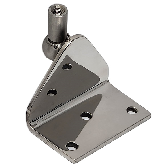
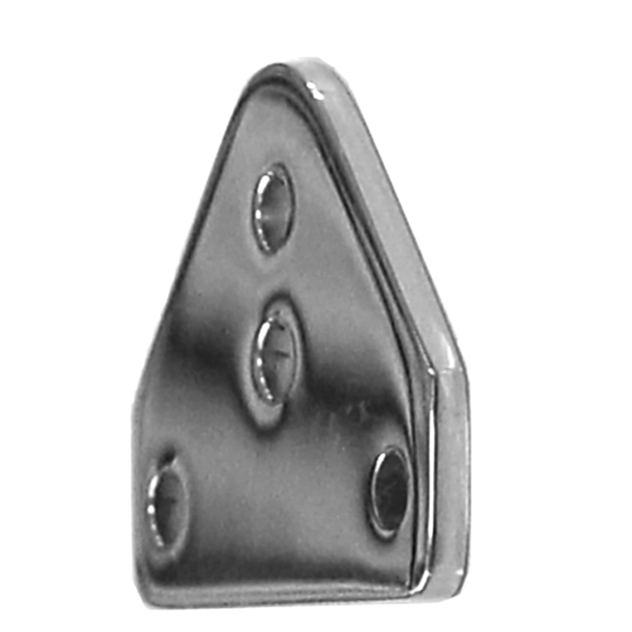
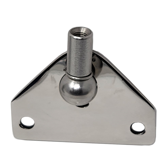
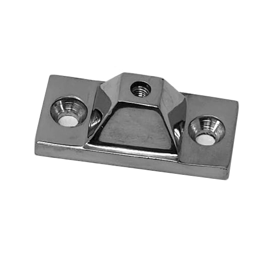
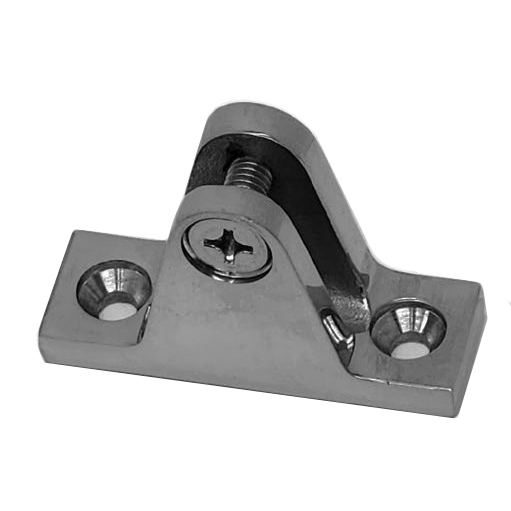
Related Products